")
Another GPZ FF
With the t-max project slowing down and the prospect of another summer coming and going without an FF to ride – and that summer being in the south of France, I decided it was time to build something – anything (with a low COG and seat-back) – to get me on the road.
When we left Ireland and the truck came to take our stuff to France, I had been planning to sell the GPZ that I had been riding while the T-Max was off the road being FFed, but at the last minute there was room for it, so to France it came.
The GPZ has been FF’d (I used the term in it broadest definition) before by several people. Arthur and Bob have both used this as a donor.
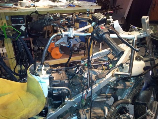
The first step is to unbolt everything, stand back and scratch the head.

I started by cutting the top frame rail to make some space to sit. After butchering the airbox I could see that my legs would still need to be too wide, or I would have to sit higher or further back.

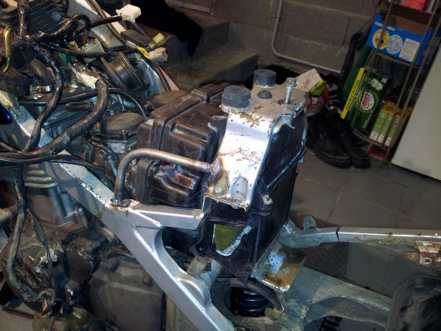
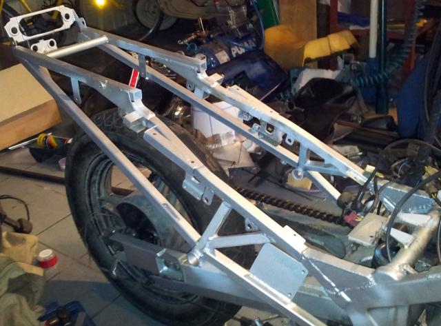
I opted to cut away the struts supporting the rear tank mount and fabricate something different. This is the new support system for the rear tank mount. These photos were taken before all the extra metal was removed. In this photo you can see that I partly cut through the rear frame so I could lower it to get the seat height down.
Next I started in the swing arm extensions. Arthur machined his. Bob extended his swing arm. I didn't have a mill and decided against the cost of getting someone to do it for me. To be honest the language barrier also scared me, so I decided to fabricate my own

The slots were made with a hole saw, a plasma cutter and a file
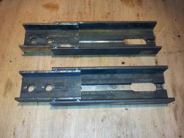
Here you can see how the extensions are made. I fabricated channel by welding angle together. The smaller piece goes inside the end of the swing arm.

Here the extension is being boxed in
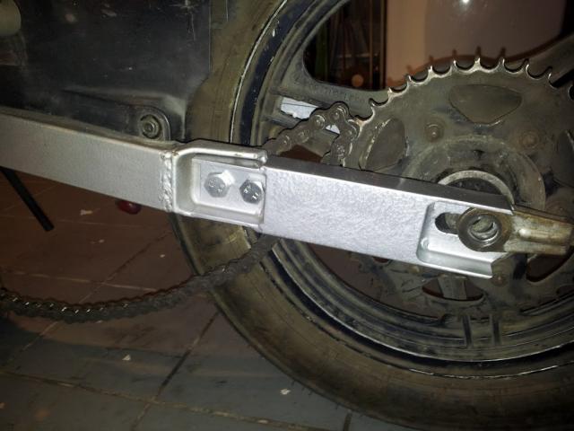
Here is the completed unit in position.
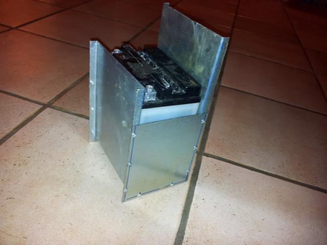
The battery box is galv plate pop-rivited together. It hangs inside the swing arm. The high side will act as a front mud-guard
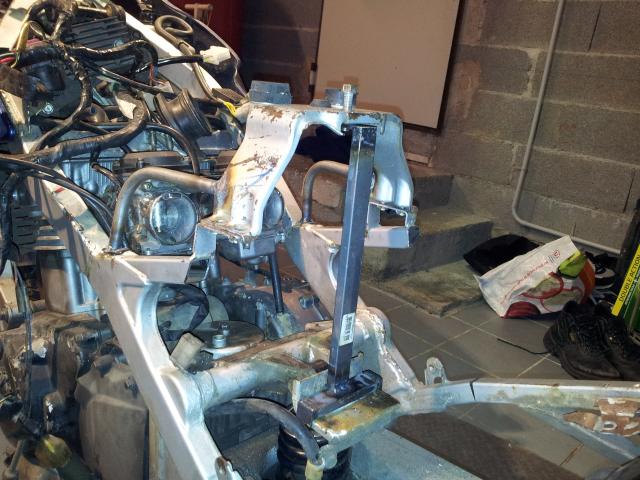
Here you can see the extra bracing that has been added under the frame to replace the support given by the upper brace that has been removed. You can also see the mounting points for the seat back.
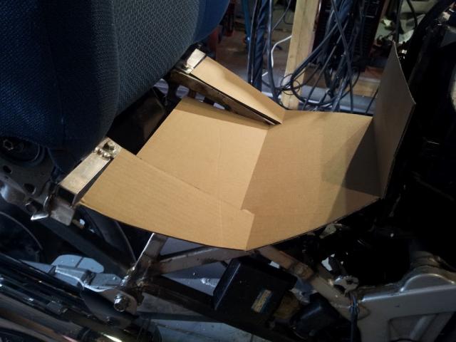
With the seat back in position, a seat base is needed. The bottom of the seat base must mate with the frame, so I mocked up the shape in cardboard
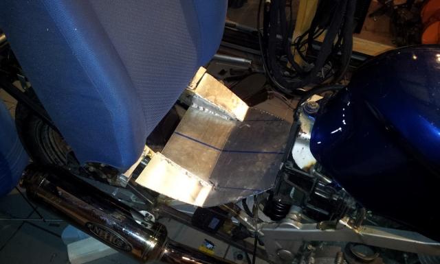
... and replicated it in aluminium

Ok so now there is somewhere to sit. The rest of the ergonomics are determined from this position. I decided to work on my hand before my feet. I put my hands in front of me into what I felt was a natural position. The handlebar ends go there. I then needed to support the handlebars there - ie in mid air.
I decided to build a Y shaped support to hold a secondary steering head. It must not cover the fuel cap and must be light, so I opted for aluminium. It must also be easily removable in case the tank has to come off on the side of the road.
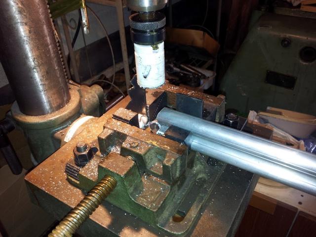
Here I am using a hole saw in a pillar drill to notch the tube
Here two of the three tubes are welded in position already. The vertical is a piece of tube I fabricated from plate as I didn't have tube the correct dimension. It is 25mm ID, so I simply belted a piece of aluminium around some inch bar and welded a seam while it was still on the bar. There is no risk of welding the aluminium to the steel and you get a beautiful internal seam. The ends were squared up in the lathe.
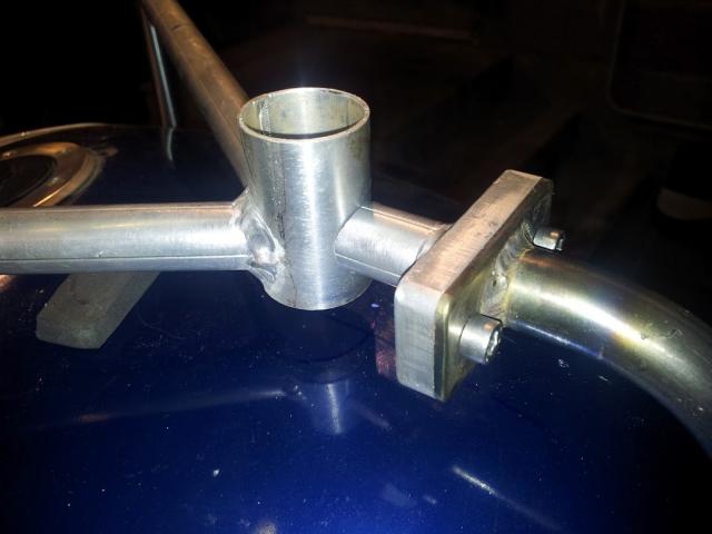
The big boss is because this was the only idea that came to mind to join the aluminium Y to the rear steel upright at the rear of the tank. Given its rather sensitive location, I wanted the steel to curve around the tank. I don't want any sharp edges between by legs if I have to stop suddenly.
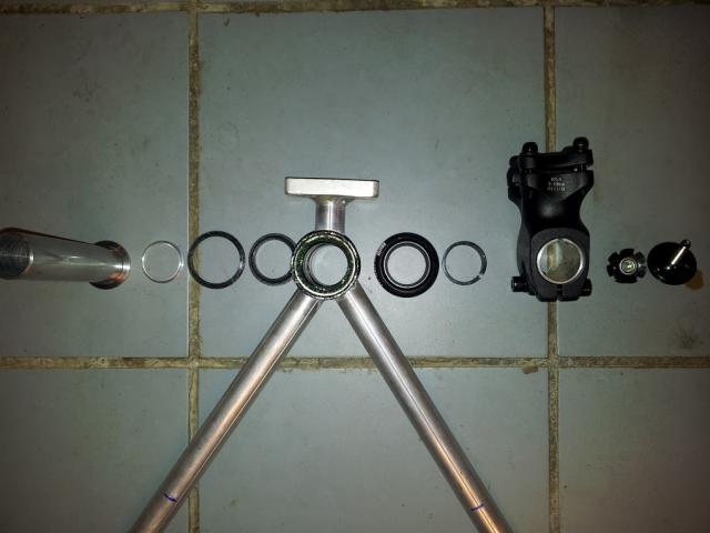
This is the secondary steering head about to be assembled. I am using an Aheadset from Cane Creek. They don't require any threading. The stem is also off a mountain bike. It is about 20 quid and it is 6061 T6 - which seems to be the cool thing to use. Its light, and cheap, so it will do me.

All those bits go together to look like this.
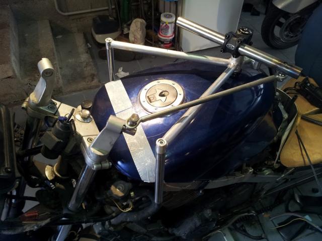
The beginnings of the handlebar and the drag link. Fortunately there is enough angularity at both ends. The steering pivit at the front is the standard rake angle. At the rear, the pivot it vertical so that the bars to not drop at full lock.
OK, so now I have a piece of straight bar pivoted just forward of where I want my hands. The handlebars on the standard GPZ are stubs that go into risers, so I need to build to attachment points to take these. I turn the attachment points, but need to connect them to the bar. I decided that the bar stubs are to be swept back 20° and down 20°. More would be nice but I was concerned about have the brake master cylinder at too much of an angle.
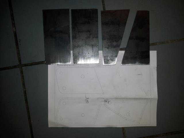
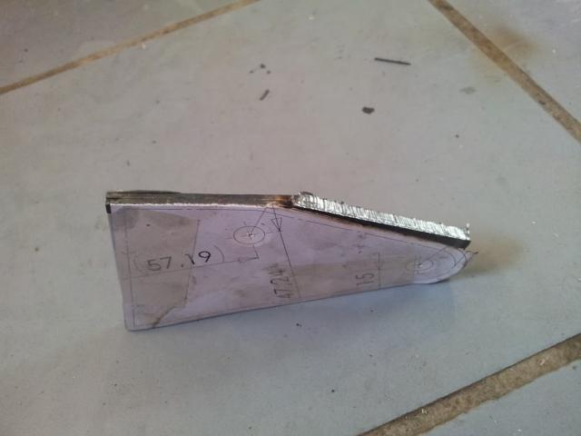
To connect these pieces I need a short piece of tube with very specific notches. This was one of the few times I resorted to CAD. I placed the pieces where I wanted them in CAD, used them to cut the joint piece then developed the tube.
Inside the development I added a curve 3.4mm smaller. I printed this pattern 1:1.
I suppose I should mention that the distance from the edge of a cut made with my plasma cutter to the edge of the nozzle is 3.4mm
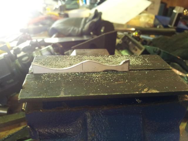
The picture above is filing a piece of scrap aluminium to the shape of the printed pattern to make a template.
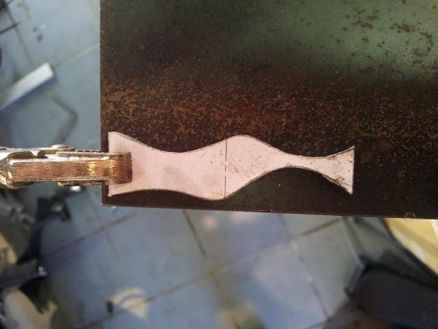
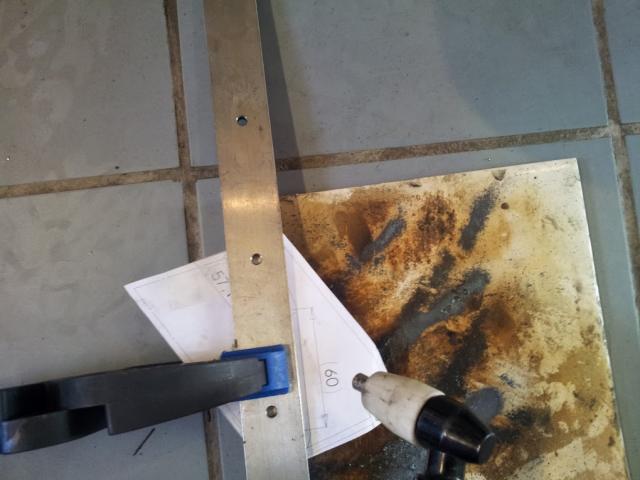
Here the template is clamped to the steel ready to cut

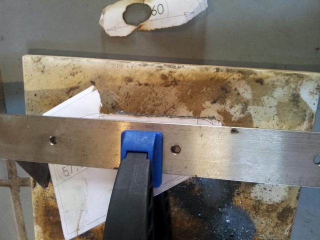
and here is the cut piece next to the template showing the actual edge and the 3.4mm offset
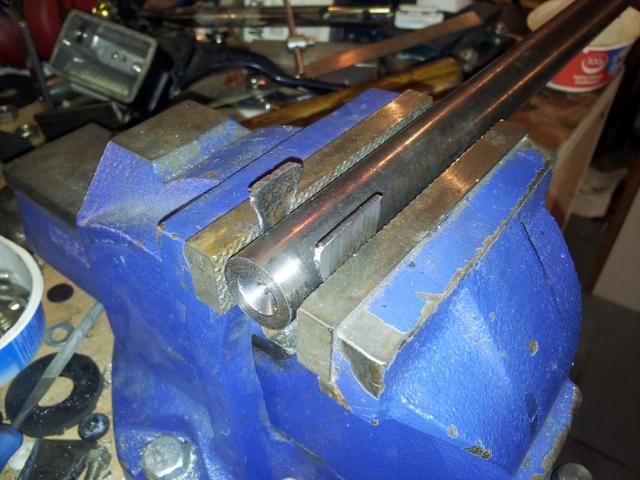
Making the tube is a matter of gentle persuasion with a hammer.

Once the seam is welded up the piece matched very nicely. One weld done, one to go.
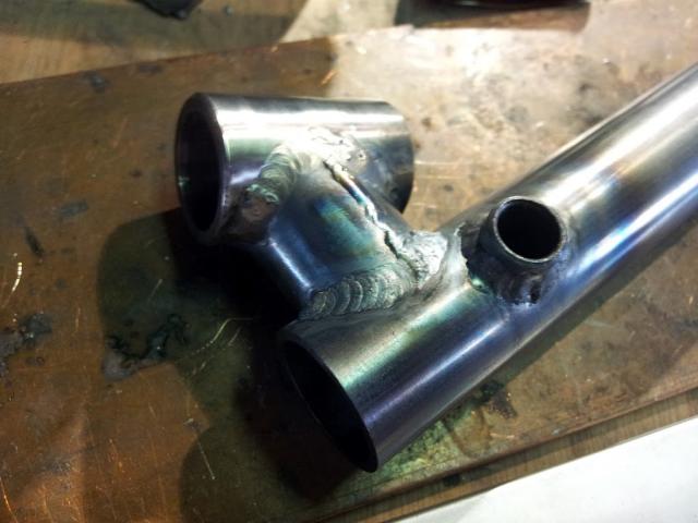
and voilà!
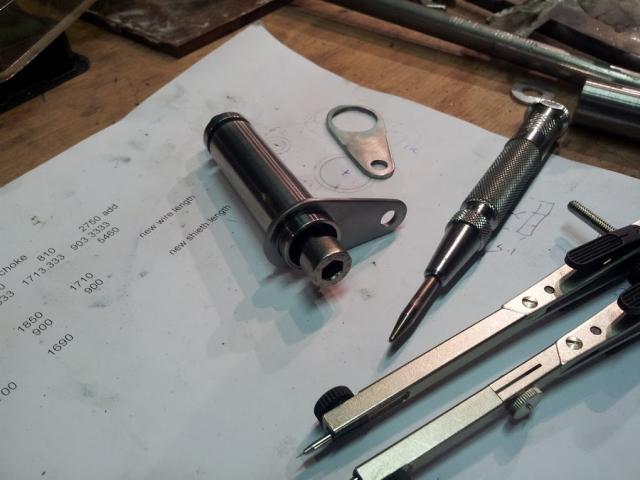
The completed handlebar in place waiting for the new throttle cables and brake hose. As I was not sure exactly what length I needed, I used a repair kit from Venhill. You get enough sheath and cable to make several cables. I found though that for cables greater than 1m the liner has to be fed in from both ends.
With a seating position sorted and handlebars in place it was possible to feel where my feet should be. I mocked up foot plates in wood to feel the position was right
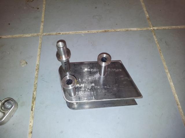
OK I lied. I used CAD again. This is a rather boring shot of the steel blanks for the new foot peg mounts.
Guide in place ready to cut
5 seconds later
The completed foot-peg mount
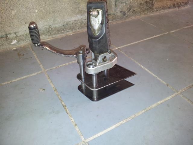
and again with the foot peg and gear change in place.
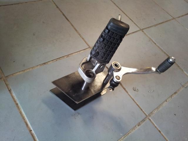
The right peg and brake pedal
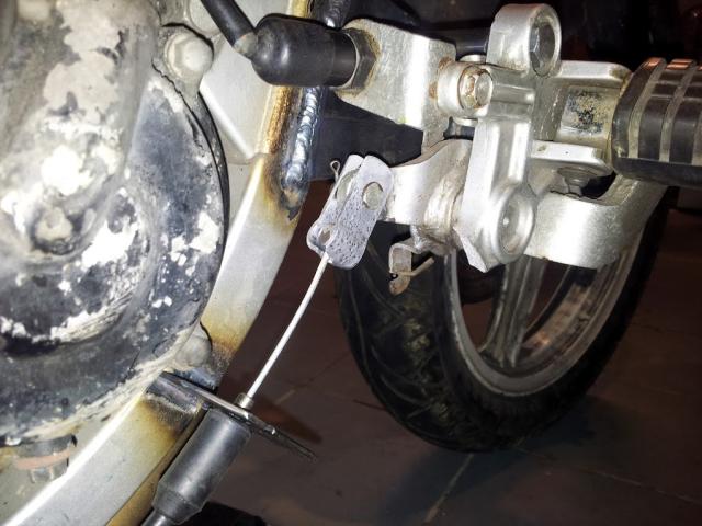
The brake cable in place.
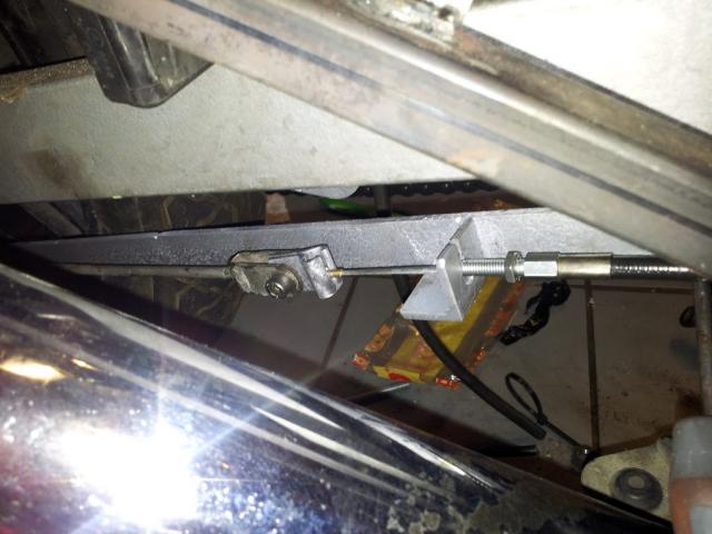
The far end of the brake cable connecting to the original brake rod.
To connect the gear pedal to the gear box I needed a redirector, and there was no straight run - the alternator was in the way. It was a good excuse to have some fun on the lathe.
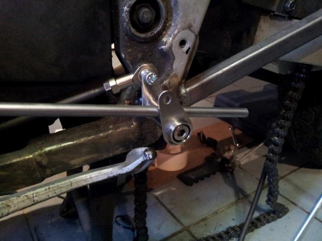
The redirector mounts on the original gear pedal mount. The new connector rod then runs forward to the new pedal location outboard of the alternator housing.
And that is it for the basics. Find a new, low, secure seat position, and move the user interface to match that position.
The project is far from finished at this point. Still to do at this point in the story, was the bodywork and tuning the suspension.
- pfouche's blog
- Login to post comments

welding/fabricating/CAD
Nice alloy welding there Peter, what set-up are you using (Inverter TIG?) I've just got MIG, so I tend to go straight from steel to GRP. Bit nervous about the stressing of your hand control mount - you'll have to avoid picking the bike up by the steering...
Actually, the only time anyone broke a Voyager steering control mount was by picking the bike up with the hand controls.
Nice fabricating too. Like the way you go from steel fab. through alloy welding and turning! I also use Cad printouts as templates, marking out directly through a CAD printout onto sheet metal is far more accurate than hand mark-out. It allows sheet metal fabrication that's absolutley accurate, self-jigging. Another CAD technique I've used with a plasma cutter is to cut out the profile in MDF, with a cnc router, including the plasma cutter allowance, and use the MDF as a plasma cutting jig. That was fabbing 10mm plate onna boat.
It may be that you've spent too much time looking at computer screens and are keen to cut metal - while I've spent a life cutting metal and find computer screens warmer and less sharp-edged... But I've found simple 2D CAD the biggest step up in hand fab.in my life. Hours spent in the warm and dry, re-iterating arrangements of illuminated lines, pay back in hours productively assembling well-fitting and minimalist stuctures in the workshop.
I understand the pleasure in hand fab. but I think anyone who believes it's some craft that shouldn't be polluted by the small screen is just going to take more time to build a heavier FF.
Holesaws are great. You can use them to cut off steel tube at an angle, so that the tube fits up immediately, perfectly, to another round tube. Really transforms tube fit-up, allows round tube to be fabbed up as fast as square tube (which is heavier, size for size). It's a fairly brutal process, vice jaws essential. Keep away from children etc. They'll cut endlessly into soid steel too, you've just got to remove the plug occaisionally. The only catch is that they're all made to an American (Starret) patent and come in 'imperial' sizes. OK for 20mm, 25mm, a pain for 30mm, or the 60mm needed to locate my steering pivot bearings.
Your swing-arm extension is a bit mighty! I use 25x50x12G (2.36mm) steel tube for forks, front and rear. In real accidents it's been shown to deform more usefully than 10g. (2.5mm) You might want to consider a top wishnbone on that fork to stiffen it up in torsion, it'll be a bit floppy otherwise and that'll affect steering precision.
Good to watch other people working!
Royce